At 5 MW, the shape of a floating solar array may still seem like a layout issue, but that is no longer true at higher capacities. At higher capacities, the shape of a floating solar array may no longer be a layout issue. A floating solar power plant at this scale requires a different approach. It is a system-architecture issue at 100 MW or 200 MW.
A reservoir is not a featureless flat surface. Depths vary. Shorelines vary. Wind fetch varies. Mooring angles vary. Water levels vary. It may be easy to approach one part of a reservoir but not another. Engineering conditions of two separate sections within a floating solar plant, even within the same body of water, can be quite different.
That is why we do not believe that large-scale floating PV should be considered simply as an increasingly large floating table.
The real issue is: where does one array end and the other begins?
This decision is much more than simply a layout for floats.
It can affect the transfer of environmental loads, the design of mooring systems, the placement of electrical components, fault isolation, technician access to equipment, and the extent of plant disruption necessary during fault conditions.
Segmentation is already visible in large Indian projects
The Ramagundam (NTPC) 100 MW floating solar power project serves as a very good example.
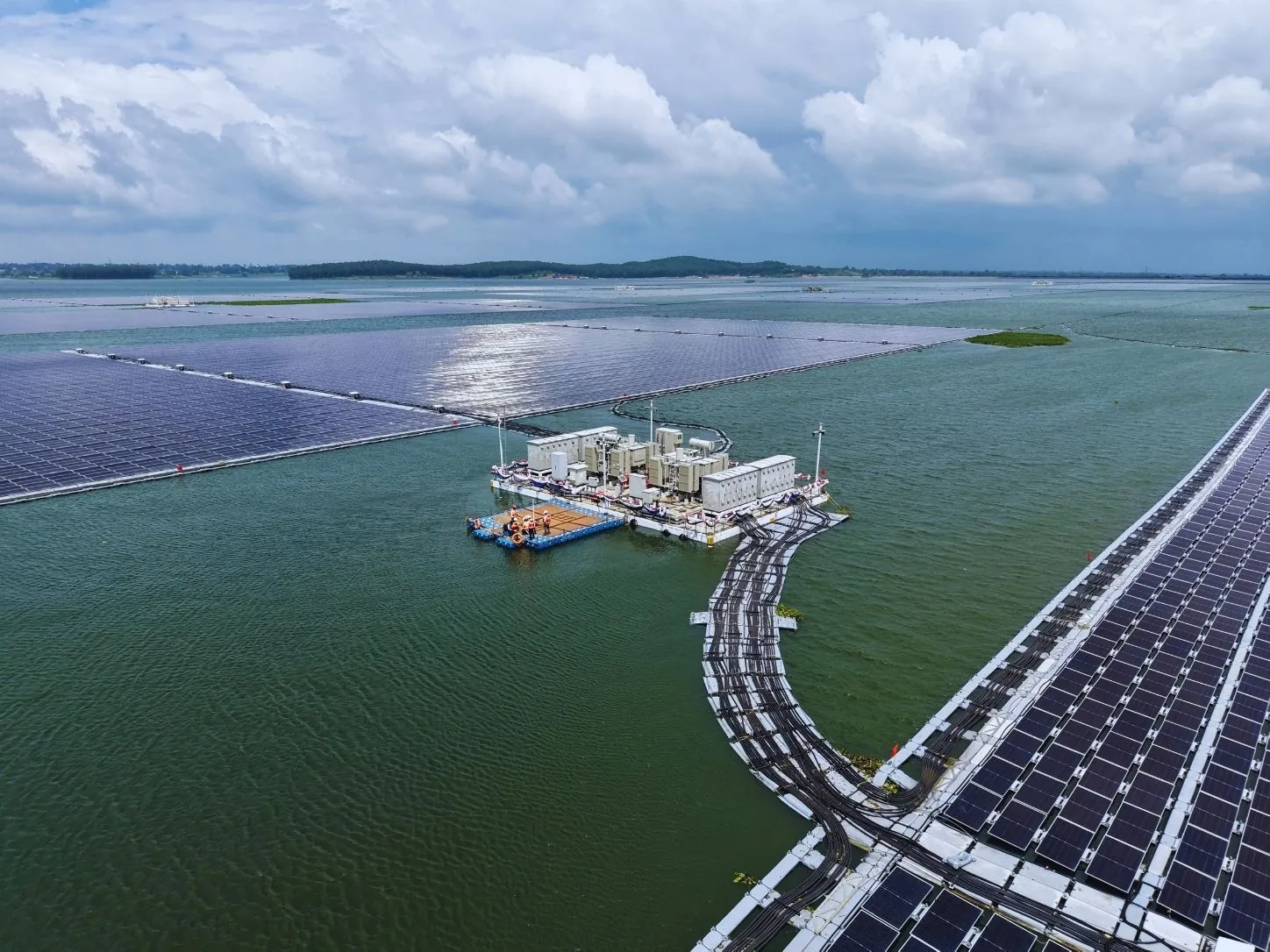
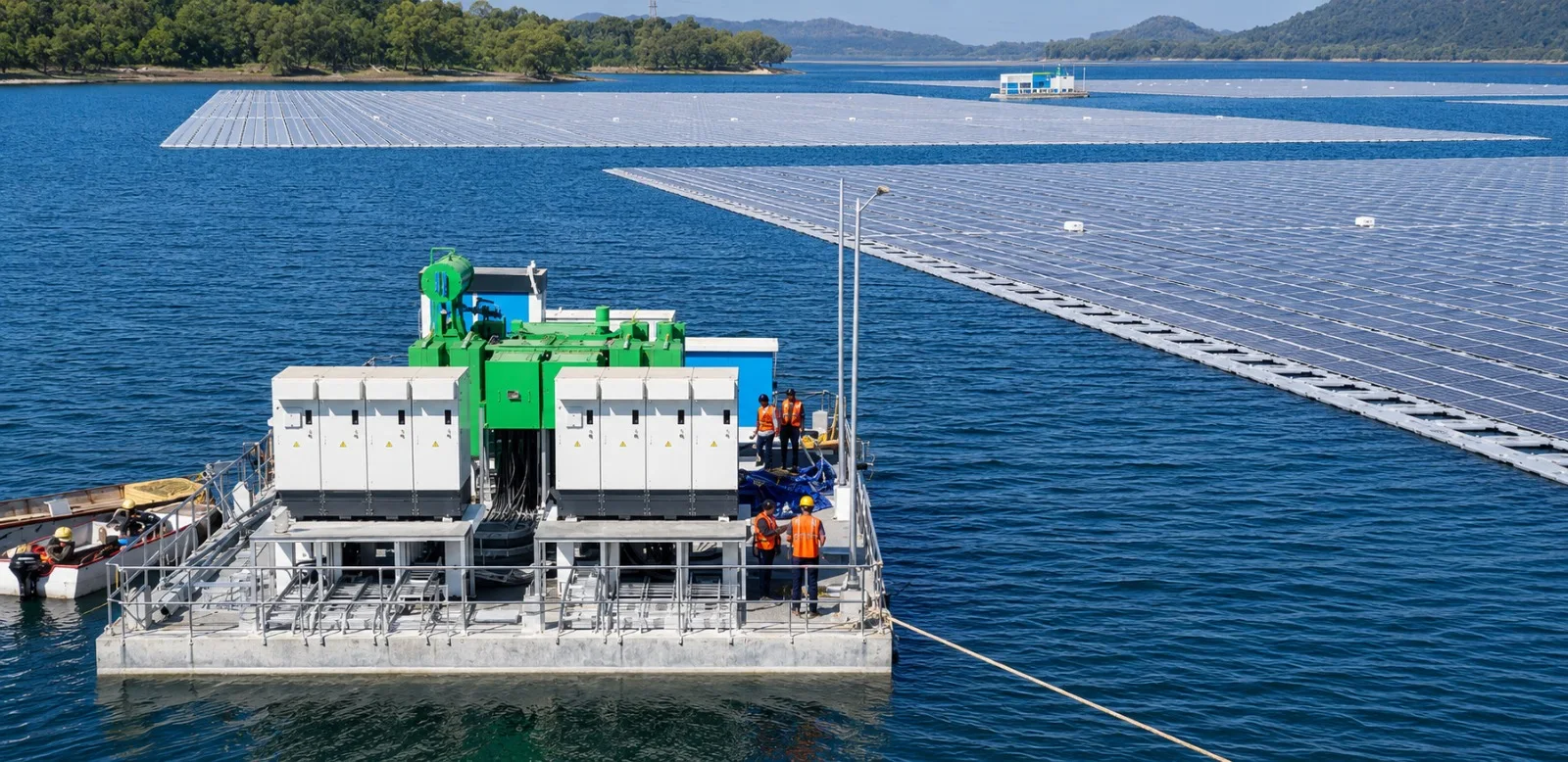
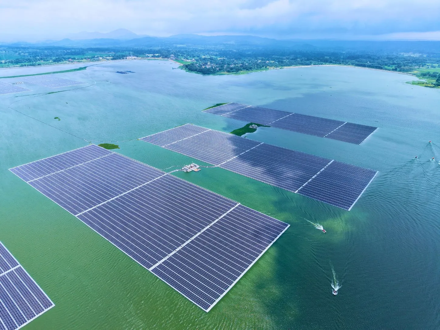
This project has not been planned as a single 100 MW floating solar power project; instead, it has been divided into 40 units, each with a capacity of 2.5 MW. In each block, there is a floating platform with around 11,200 modules, along with an electrical platform that contains an inverter, transformer, and high-tension breaker.
| Ramagundam design parameter | Reported configuration |
|---|---|
| Total plant capacity | 100 MW |
| Number of array blocks | 40 |
| Capacity per block | 2.5 MW |
| Modules per block | ~11,200 |
| Block-level equipment | Inverter, transformer, HT breaker |
| Reservoir area used | ~500 acres |
| Mooring system | HMPE rope connected to reservoir-bed dead weights |
This does not mean that 2.5 MW is the universal correct island size. It is not.
It does demonstrate something much more important: even at 100 MW, plant capacity and floating-island size do not have to be the same thing.
100 MW of generation does not mean one 100 MW structural object
This demonstrates something more significant: a 100 MW system does not necessarily need to be a single floating island of the same capacity.
A floating PV system is flexible and responds to wind, waves, and current. These forces have to be transferred through floating components and connectors before reaching the anchor lines. The engineering issue is not simply how many additional modules can fit on an island as its size increases.
It becomes:
- How are loads distributed through the island and into the mooring connections?
- What happens when wind direction changes or reservoir level changes the mooring geometry?
- Can local component failure remain local rather than creating a wider structural problem?
- How easily can a damaged section be inspected, approached and repaired?
- Does increasing island size actually reduce cost after stronger mooring, longer internal routes and more difficult O&M are included?
These issues have become increasingly clear in FPV engineering practice. The DNV Floating Solar Energy standards for 2026 especially emphasize the structural design of floats and station keeping, including design loads, load combinations, failure analysis, and systems designed to minimize station-keeping failures.
Research is also being done to better understand the issue of island size. In 2025, Ocean Engineering studied FPV islands ranging from hundreds to thousands of floats and how wave loading, hydrodynamic response, and mooring requirements depend on the size of the island. In particular, an upper bound on the size of the island was determined as a function of the minimum breaking strength of the mooring line.
What changes when the plant is divided into engineered blocks?
Segmentation creates boundaries.
Used properly, those boundaries can serve several engineering functions at the same time.
| Design layer | One very large continuous array | Segmented utility-scale architecture |
|---|---|---|
| Structural response | Larger interconnected load-transfer domain | Loads can be resolved within defined islands |
| Mooring | Large common station-keeping problem | Mooring can be adapted by island/location |
| Electrical design | Greater dependence on shared routes and equipment | Natural inverter/transformer/feeder blocks possible |
| Fault consequence | Local problem may affect a larger operating area | Isolation can be designed around smaller plant sections |
| Maintenance | Long internal access distances | Defined access corridors and service zones |
| Construction | Large interconnected installation sequence | Repeatable block-by-block assembly possible |
| Commissioning | Large system boundary | Progressive block commissioning becomes possible |
| Future intervention | More interfaces may need to be disturbed | Individual blocks can potentially be isolated |
Segregation need not lead to redundancy. Common-mode failures can happen from common MV installations or from substations or export cables.
But it provides an important engineering benefit: segregation creates defined boundaries for redundancy and isolation.
Mooring is one of the strongest reasons to think in islands
Moorings by their very nature are site-specific designs.
According to The World Bank Floating Solar Handbook, the following interdependent factors make up the layout considerations: water depth, reservoir bed, fluctuation in water levels, environmental forces, cable route, maintenance approach and the distribution of FPV sections in the water body.
It has been explicitly stated that an FPV system comprises large floating islands or sections. This is essential because the "best" mooring solution at one end of the reservoir may not be suitable a few hundred metres away.
Imagine a 150 MW project crossing areas with:
- a shallow bank on one side but significantly greater water depth elsewhere;
- variable bed material affecting anchor selection;
- different exposure to prevailing wind and wave fetch;
- large seasonal water-level variation;
- existing intake structures, navigation zones or reservoir infrastructure.
Trying to put everything into one continuous mechanically constructed raft can risk compromising design conditions at both the local and plant levels.
A compartmentalized arrangement, however, can respond more effectively to the conditions of the reservoir.
This is where floating solar engineering should be heading-arrays should align with engineering zones of the waterbody, not a square or rectangle.
Electrical segmentation should follow the same logic
Mechanical islands and electrical blocks do not have to match on a one-to-one basis, but they should be designed in coordination.
For example, in the Ramagundam case, each 2.5 MW block has its own inverters, transformers, and high-voltage switchgear, allowing the electrical equipment to align with the floating island. This is a fundamentally different approach from treating the entire 100 MW as a single generation surface.
For a utility-scale floating solar plant, sensible electrical segmentation can support:
- isolation of equipment for maintenance without unnecessarily removing large portions of capacity;
- clearer SCADA visibility at block level;
- easier comparison between otherwise similar arrays;
- faster identification of abnormal string, inverter or transformer performance;
- staged testing and commissioning during construction;
- defined cable-routing corridors between floating generation blocks and the collection system.
This last point becomes increasingly important on water.
The World Bank states that FPV Electrical System is being set up in a high-humidity condition, and proper care needs to be given to cables during the movement of the FPV System as any carelessness would lead to problems of mechanical functioning.
For this reason, cable architecture, beyond the one-line electrical diagram, is important in a large floating solar power plant.
Segmentation is also an O&M decision
The plant will require operation, inspection, and maintenance throughout its operational life.
The modules and mooring elements will need regular inspection, cables will have to be checked, and electrical equipment will require maintenance and occasional repairs. There may be a need for replacement of floats and connectors.
Unlike a ground-mounted plant, technicians cannot simply drive to the affected table when a problem occurs.
The specific challenges associated with the operation and maintenance of a floating PV system, as per the World Bank FPV guidance, include difficult access to components, mechanical wear due to water flow, corrosion, and flexing. It states that in plants which do not have walkways, there will be a need for boats and specialized equipment just to get to the modules.
This changes the economics of the layout.
At Floatex Solar, we believe utility-scale design should ask before block dimensions are frozen:
- Can a crew reach the centre of every island safely?
- Can one block be electrically isolated without creating unnecessary plant-wide downtime?
- Can a module, float, cable or mooring connection be replaced without dismantling unrelated sections?
- Is there adequate boat access around critical perimeter areas?
- Can SCADA identify the affected block before a physical inspection begins?
- Does the block geometry still work at minimum and maximum operating water levels?
- Can emergency response reach the affected area without crossing a large energized floating field?
These are not secondary O&M questions. They belong in concept and detailed engineering.
There is also such a thing as over-segmentation
With segmentation, it can be tempting to assume that more segmentation is always better.
That approach can be just as problematic.
The additional islands can serve as mooring lines, anchors, cable transition areas, switchgear interfaces, platforms, installation spots and inspection points.
The same trade-off applies to floating-solar station-keeping: it must provide sufficient redundancy and load distribution while minimizing component count and connectivity to simplify installation and reduce potential failure points.
Thus, the engineering challenge is not to build the smallest possible island.
It is about identifying the optimal repeatable block for the reservoir.
It may be 2.5 MW in one case, 5 MW in another and any other completely different approach in yet another location. The capacity is NOT a universal constant in the design.
Utility-scale FPV needs a different definition of scale
The floating solar opportunity has now gained significant traction in India. In this regard, NISE estimates that the country has around 102.18 GWp of technically feasible floating solar potential across suitable inland water bodies.
Scaling FPV, however, is not simply a question of scaling up today's floating solar arrays.
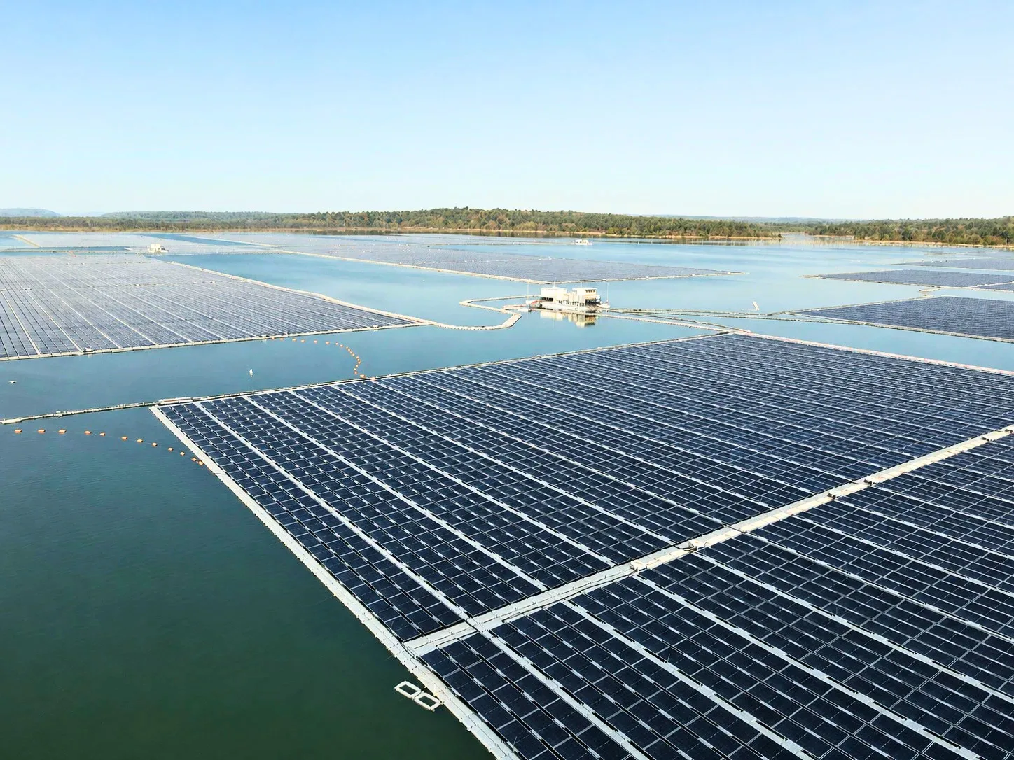
A 200 MW reservoir project does not necessarily require a single 200 MW floating array. This distinction makes all the difference.
A good utility-scale floating solar power plant should be designed more like an integrated infrastructure project.
It has to be a well-coordinated structure consisting of blocks that can be easily controlled, matched to their specific loads, integrated into the plant as a whole, and designed so that a localized problem does not unnecessarily become a plant-wide problem.
That is the route from floating panels to floating infrastructure.