A faulty connector is a component failure. If a broken connector causes the neighbouring connectors to exceed their limits, it is an array problem.
This is a key principle in Utility-Scale Floating Solar design.
Designing a 25-year Floating Solar power plant without considering that all floats, connectors, shackles, mooring lines, cable glands, fuses and inverters will not remain in the same condition throughout the design life is a risky proposition. Components age. Fasteners loosen. Cables chafe. Materials fatigue. Loads can be much higher than normal when extreme events occur.
The engineering goal, then, is not simply to prevent all failures.
It is also to ask:
When one component does fail, what does the rest of the plant do next?
Here at Floatex Solar, we consider the post-failure condition to be an integral part of the design.
The dangerous part of a failure is often the new load path
Floating arrays are networks of interconnected systems.
Remove one structural connection, and the environmental load does not disappear. The array remains influenced by wind, current and waves. The forces previously carried by the failed component must be transferred through another load path.
Recent research has demonstrated this effect.
A study of a lattice-type floating photovoltaic array was conducted under coupled environmental loading in 2025. The tension in a connector aligned with the wave direction was found to increase by 64.3% when another connector failed. It was also noted that neither wave height nor wave period had as significant an effect on connector and mooring-line tension as wave direction in the cases investigated.
A separate experimental and numerical study conducted in 2026 confirmed this overall finding. Connector failure changed the motion characteristics of the floating multi-module system, increasing surge, sway and yaw around the affected modules and, consequently, peak tension in unaffected modules connected across the failed connection.
Therefore, a component should not be qualified solely on the basis of the question:
Will it hold up to the intact-array load?
Another question that we must ask is:
If that component is removed, can the system still operate safely?
Not every single failure has the same consequence
A useful starting point is to map credible failures to their immediate and secondary effects.
| Possible local failure | Immediate effect | Potential escalation if not contained |
|---|---|---|
| Float or buoyancy-element damage | Local loss of buoyancy/freeboard | Panel misalignment, water contact, increased connector loads |
| Inter-float connector failure | Load path interrupted | Higher loads in neighbouring connectors, collision or separation |
| Mooring-line failure | Local station-keeping capacity reduced | Array displacement and overload of remaining moorings |
| Anchor movement/failure | Mooring geometry changes | Increased excursion and redistribution across adjacent lines |
| DC cable damage | Electrical fault or insulation degradation | Ground fault, arc risk or loss of a wider circuit |
| Junction-box water ingress | Local equipment fault | Protection operation, corrosion or loss of connected strings |
| Inverter failure | Generation block offline | Unnecessary wider loss if the electrical architecture lacks isolation |
| Earthing/bonding connection failure | Local continuity lost | Multiple structures may lose bonding if connected purely in series |
Failure-containment engineering is not about making all these events safe.
The aim is to prevent their consequences from spreading unnecessarily far.
This principle has since been captured by formal FPV engineering guidance. The 2026 structural standard, DNV-ST-C108, clearly correlates the level of design and testing with the consequences of float failure, including safety and consequence categories and the identification of relevant failure mechanisms.
The accompanying DNV standard for station-keeping goes further. According to the standard, a failure modes, effects and criticality analysis (FMECA) is the foundation for station-keeping risk assessment, while the requirements for system configurations are intended to reduce the risk associated with failures.
This represents an important shift in Floating Solar design.
Mechanical redundancy does not mean simply adding more ropes
Redundancy is often misunderstood.
Even when additional mooring lines are installed, the existing mooring system must still provide sufficient redundancy. If one line, one anchor or one connection becomes detached, the remaining mooring system must be able to safely take on the additional load.
Otherwise, the added components may simply provide additional load paths that have never been examined under damaged conditions.
For a Utility-Scale Floating Solar plant, mechanical containment can involve:
- Damaged-condition analysis: Recompute the structural and mooring model with reasonable components omitted, rather than analysing only the intact model.
- Alternate load paths: Provide alternate paths around the loss of a critical connection, and make sure that the loss of one path does not leave an entire section of the array effectively uncontrolled.
- Reserve capacity: Normal operating loads are not necessarily the loads that surviving connectors, anchors and mooring lines must be capable of carrying after a failure.
- Array segmentation: Avoid mechanically spreading unwanted motion through a very large connected field of islands by creating defined boundaries.
- Physical clearance: Provide sufficient clearance for a damaged array to move without colliding with nearby islands, intake structures, banks and electrical platforms.
- Failure-tolerant connections: Consider connection safety beyond ultimate tensile strength (UTS), including cyclic loading, fatigue and environmental degradation, while also considering whether connections can be inspected and replaced.
The goal is not infinite redundancy.
It is about designing for an expected damaged state.
If the array moves when Mooring Line 7 is lost, the engineering analysis should show where the array moves, how the additional load is redistributed, how far the array moves and whether the affected elements remain within damaged-condition limits.
Redundancy does not mean assuming that another component will take the load. This must be demonstrated through analysis.
Electrical containment follows the same philosophy
The mechanical array is just one component of a plant.
Electrical faults are more complex in a water-based environment because of water movement, high humidity, cable flexing, chafing, potential submersion, corrosion and water ingress.
The World Bank/SERIS Floating Solar Handbook for Practitioners has clearly highlighted cable abrasion as a risk for FPV because cables can rub against moving structures. The maintenance instructions state that cables and connectors should be checked monthly to ensure they are secure, inspected for chafing and insulation deterioration every three months, and subjected to insulation resistance and thermal testing annually.
Inspection alone does not provide containment.
Protection architecture has to make it possible to isolate the faulty section.
It is interesting to note that the same handbook states that faults in protective devices result in the shutdown of the AC and DC electrical subsystems, rather than necessarily resulting in the loss of the entire generating plant. It also specifies the need to verify isolation switches, fuses, breakers, residual-current protection and earth-fault devices.
This leads to a useful design rule:
Except where impractical, the electrical isolation boundary should be aligned with the fault.
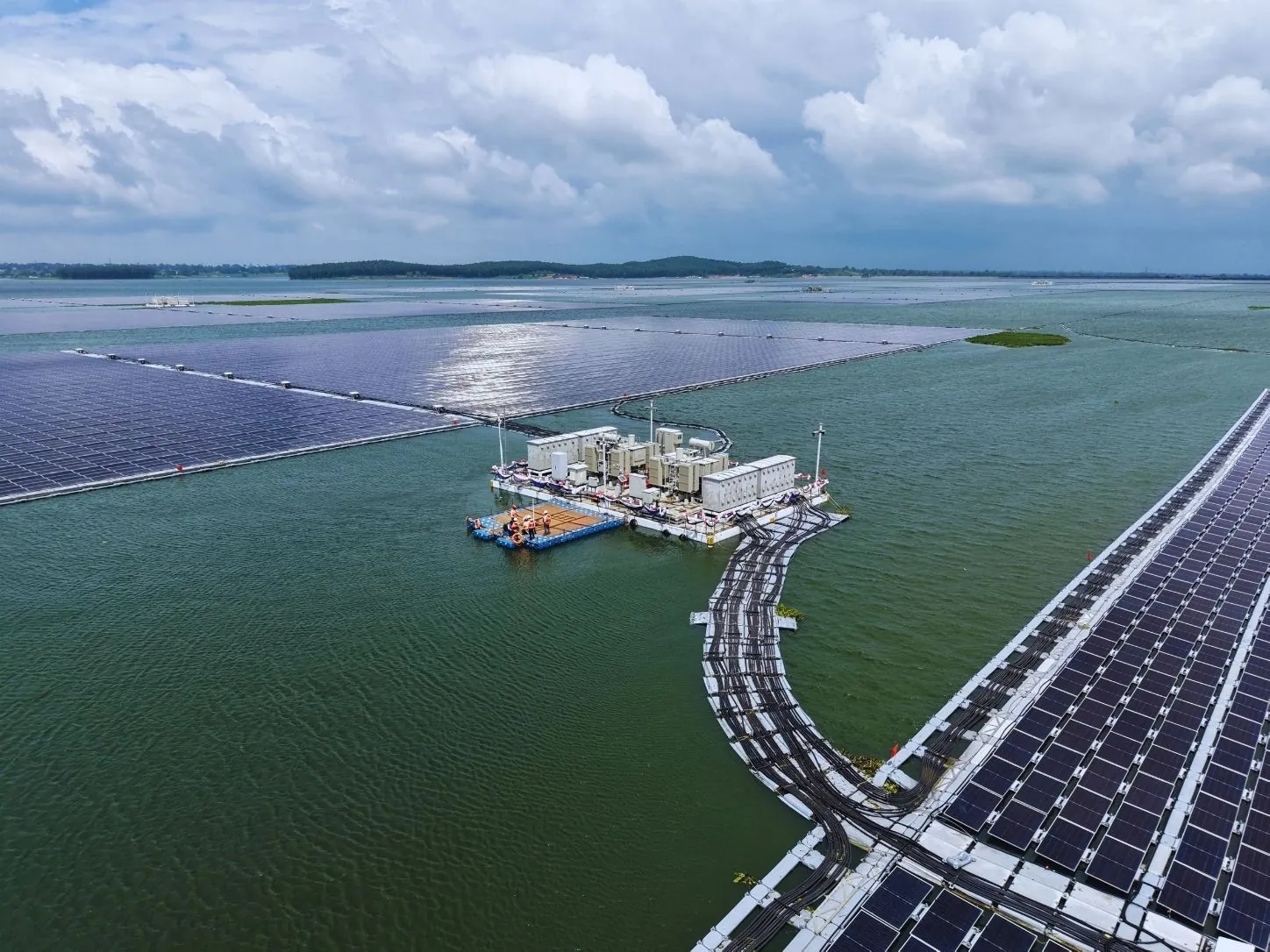
A fault in one string should not lead to the loss of an entire inverter block unless necessary. An inverter block fault should not take an entire floating island out of operation unless it is required. Tens of megawatts should not be lost because of an electrical problem on a single island if that island can be safely isolated through the collection architecture.
A surprisingly good example: grounding continuity
Small design details can be critical to effective failure containment.
A particular problem with grounding in FPV is addressed in the World Bank handbook.
When module frames are simply connected in series, a failure of one bonding connection can cause a loss of continuity in the ground circuit downstream. In an alternative configuration, the handbook suggests an architecture in which a primary grounding conductor is installed on the floats and each module is independently connected to the primary grounding conductor.
The key consequence is that if a bonding lead is accidentally broken, other module frames connected in series with it will not necessarily lose their connection to the main grounding conductor.
The difference in the number of components is minimal.
Yet the resulting failure behaviour is entirely different.
That is the principle of local-failure design.
Normal-state design and damaged-state design are different exercises
For large projects, we find it useful to distinguish explicitly between the two.
| Engineering question | Intact condition | Local-failure / damaged condition |
|---|---|---|
| Mooring | Are design tensions acceptable? | What happens after one critical line or anchor is lost? |
| Connectors | Can connectors carry environmental loads? | Where does the load transfer after one connector breaks? |
| Float system | Is buoyancy/freeboard adequate? | Can neighbouring elements tolerate local buoyancy loss? |
| Island geometry | Are operating excursions acceptable? | Can the damaged island avoid adjacent structures? |
| DC architecture | Does the plant operate efficiently? | How much generation must be isolated for one fault? |
| Earthing | Is continuity provided? | Does one broken connection interrupt multiple downstream elements? |
| Monitoring | Can we measure plant performance? | Can the failed section be identified quickly enough to intervene? |
| Maintenance access | Can equipment be serviced? | Can the damaged component be reached without destabilising adjacent systems? |
The second column helps get a plant commissioned.
The third helps ensure that a local fault remains local.
Failure containment starts before detailed design
That is why we believe that FMECA should not be performed only after the layout has been finalised.
It needs to be part of the system architecture.
For concept and detailed design reviews, we want to ask the following questions:
- What are reasonable single-component failures for this FPV technology?
- What are the failures that affect the global load path?
- Which components become more highly loaded following each failure?
- Are there potential progressive connector failures if one fails?
- What happens when a mooring line or anchor breaks?
- Does the station-keeping path have another independent route?
- For each possible fault, what is the electrical protection?
- What is the MW loss associated with that protection?
- Which failures are obvious in the SCADA system, and which are not?
- Is the affected part physically accessible and replaceable?
- What happens if the initial failure is not detected and a second component fails?
In particular, attention should be given to that final question.
Redundancy is redundancy only when the backup path is healthy.
In the event of one mooring line failing without notice, the plant may continue operating, but the other mooring lines may not necessarily be the ones intended to carry the same spectrum of loads. Despite normal generation, the plant may already be operating in a degraded condition.
Thus, failure detection becomes an essential part of the redundancy strategy.
O&M is the second half of failure-tolerant design
While a design can be used to create an alternate load path, operations need to know when that alternate path is being used.
The World Bank's FPV guidance suggests half-yearly surface visual inspections of mooring components for signs of corrosion, broken wires, loose strands or other signs of degradation, as well as periodic inspection of submerged anchors and checks of mooring-line tension. It also suggests regular testing of float buoyancy, connectors, fastening systems and structural integrity.
This is important because progressive failure often begins with gradual degradation.
It may start with a single broken link that creates an increased cyclic demand on the next link.
Recent studies provide further evidence of this risk. Under the investigated conditions, connectors oriented in the direction of wave propagation in a 2026 high-fidelity simulation of a modular FPV system experienced forces 3–5 times greater than those on the transverse connectors.
It is therefore not advisable to consider all components equally critical during inspection.
The design analysis should help the O&M team identify, among other things, where the load is concentrated, which failure redistributes the load, and which parts of the design deserve greater attention.
At utility scale, failure boundaries need to be intentional
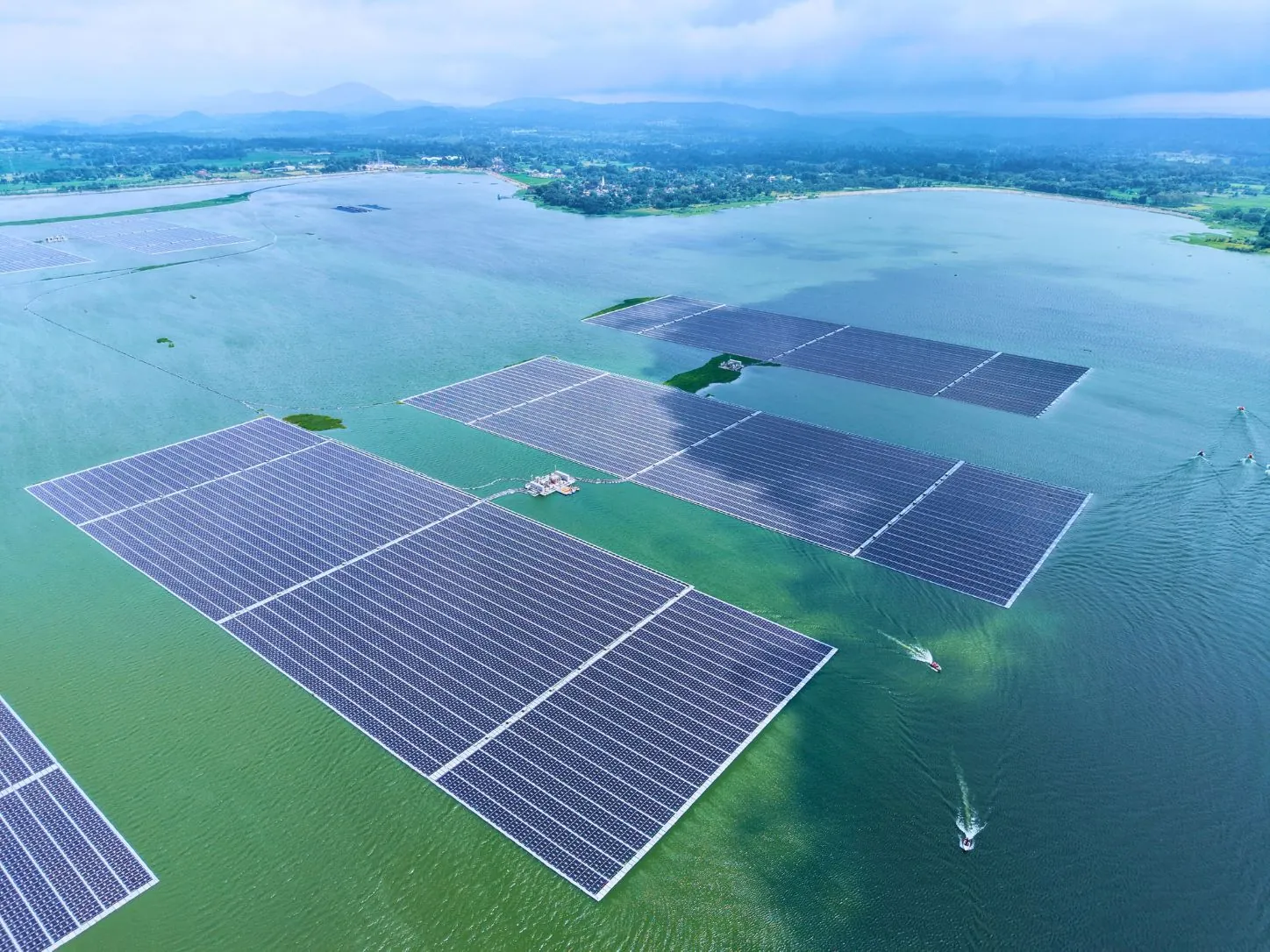
The larger an FPV plant becomes - from a few megawatts to tens of megawatts and beyond - the less justified it is to retain the same consequence boundary for each of the plant's structural or electrical subsystems.
Scale should allow for repetition without creating unnecessary interdependence.
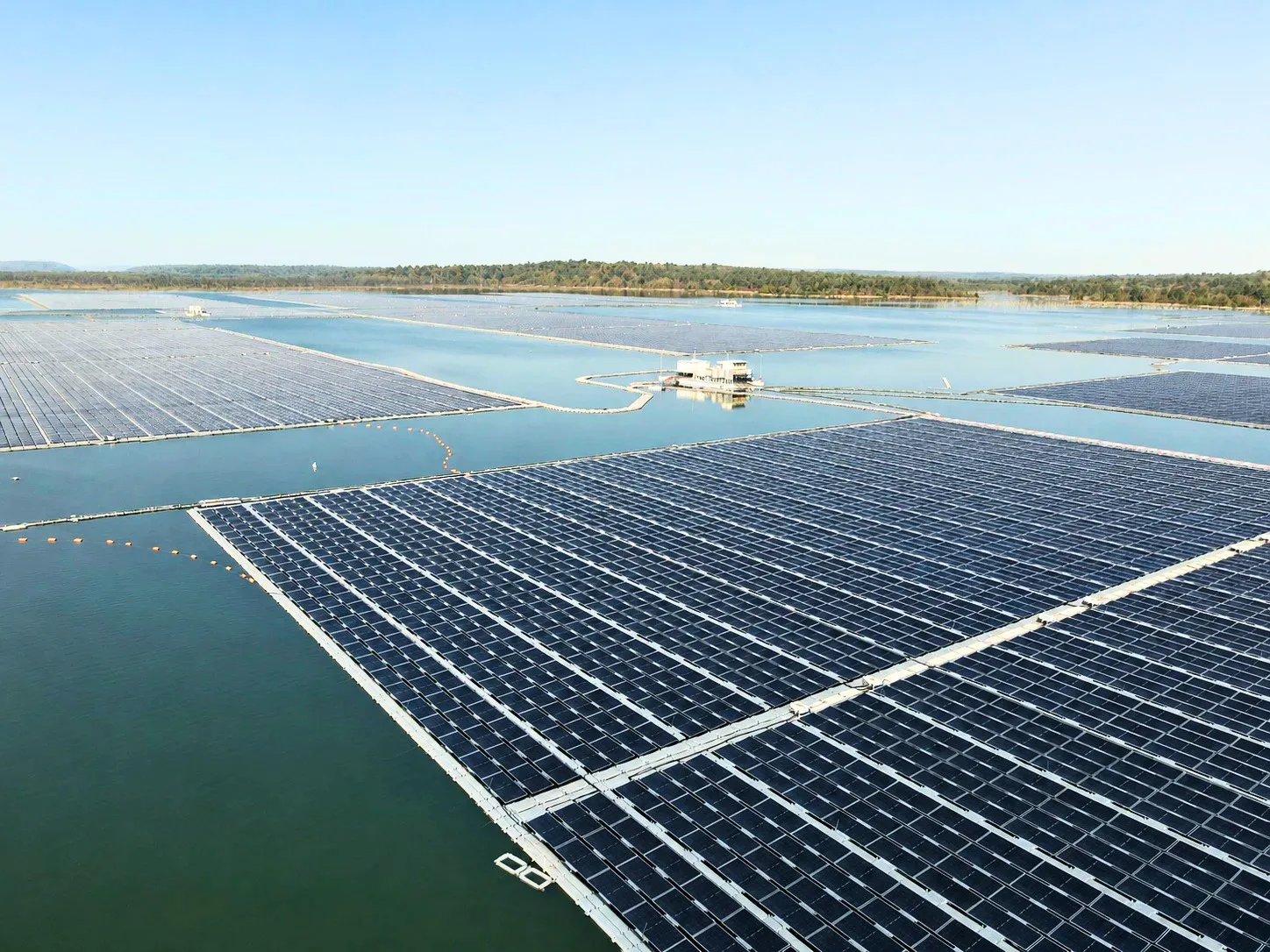
Many structural islands, mooring zones, inverter blocks, feeders and isolation points could exist within a single 100 MW Floating Solar power plant and still be considered a single generating asset.
This approach provides engineers with something very valuable:
deliberate points where failure propagation can be halted.
These should be intentional boundaries.
They can be established between floating islands and mooring zones, as well as at connectors.
They can also exist at string connections and combiner boxes, at inverter blocks, at MV feeders and even within the grounding architecture.
This configuration will vary depending on the reservoir, technology and other project-specific conditions. While the current DNV FPV standards are performance-based and do not set a single prescriptive standard, they do clearly indicate that structural consequences and failure mechanisms, as well as station-keeping failure scenarios, should form part of the engineering basis of a floating plant.
The goal is not a plant that never has a component failure
That would be the wrong reliability target.
As time goes on, parts will need to be replaced. Some may fail before the end of their intended service life. The system will also be subjected to extreme environmental events that differ from normal operating conditions.
Therefore, a strong Utility-Scale Floating Solar plant must not only withstand the environment in which it is expected to operate but also fail in a controlled manner.
- A connector failure should remain a connector problem.
- A damaged cable should remain an isolated electrical-section problem.
- The loss of a mooring line should not result in uncontrolled array displacement, but rather in a defined damaged-condition response.
- An inverter fault should only remove the affected generating block from service.
At Floatex Solar, we believe that the measure of reliability in a utility-scale FPV plant is not whether individual components can fail, but whether the first local failure determines what fails next.