A floating solar power generation report may look convincing, but does it answer a key engineering question: how much power can modules generate when mounted on floats over water rather than on fixed racks on land?
Understanding floating solar energy yield requires evaluating how these systems perform under actual water-based installation conditions.
The electrical conversion process is still photovoltaic. Energy production still depends on solar resources, module characteristics, temperature, shading, wiring, and inverter behaviour. However, the supporting float system affects some of these factors. Its geometry affects module elevation and tilt, its layout influences ventilation and shading, and its connections determine how the array responds to water movement.
Instead of abandoning traditional PV modelling or automatically assuming a "cooling bonus" for floating solar, the better approach is to use existing PV models with realistic assumptions. This means establishing a conventional baseline, replacing inappropriate assumptions with evidence from specific sites and designs, and clearly identifying the remaining uncertainty. This approach helps produce a more reliable estimate of floating solar energy yield.
Begin with a Conventional PV Model - but Do Not Stop There
A reliable starting model should include representative weather data, the proposed DC capacity, module and inverter specifications, array orientation, shading, electrical losses, and operating conditions. For this baseline, software can be used to calculate plane-of-array irradiance, cell temperature, and conversion losses. Software such as PVsyst can perform these calculations.
It is helpful to compare systems with the same module technology, capacity, resource period, and electrical boundary but different installation assumptions. If the tilt differs, row spacing changes, or loss allowances are inconsistent, an apparent floating-solar advantage could result from one of these factors rather than from the water itself.
The model should show the annual specific yield (kWh/kWp), expected AC generation, performance ratio, and a clear breakdown of energy losses. Identify the energy supplied by the inverter and the energy delivered at the contractual metering point, as there may be transformer losses between these two points.
The next important step is to determine which baseline inputs depend on the actual floating structure.
How Floats Change the Energy-Yield Assumptions
Floating pontoons do more than support the panels. The modules, their connections, and the supporting structure work together as an engineered system. Four key features should be included in the model:
- Space under each panel and rear-side ventilation: The space beneath each panel and the freedom for air to circulate depend on the float and support geometry. These factors can affect heat transfer and operating temperature.
- Support arrangement: The support structure may limit the tilt angle, row spacing, and water coverage available for each module. These factors can affect the amount of sunlight reaching the modules and the shading between adjacent modules.
- Reflective surroundings: Water, exposed float surfaces, and nearby structures affect front- and rear-side irradiance differently. Do not reuse the albedo setting for a ground-mounted system without checking the surfaces and conditions the floating modules will be exposed to.
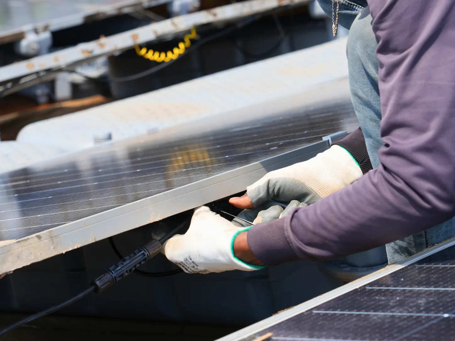
- Movement and mooring: Float connections and mooring systems may allow limited movement. If site conditions could cause changes in pitch, roll, or module orientation, these effects must be assessed rather than assumed.
The type of system must also be considered. If an air-cooled module is mounted above a pontoon, it should not be assigned a thermal coefficient based on a design in which the module directly contacts the water. Similarly, evidence from an open, well-ventilated structure may not apply to a low-clearance installation.
Float selection should therefore be part of the energy-modelling process. Instead of focusing only on the material used, such as HDPE, the model should account for measurable factors such as float geometry and operating conditions. These inputs directly influence floating solar energy yield and should be considered during the modelling process.
Model Temperature Without Assuming Free Cooling
The power output of PV modules tends to decline as cell temperature increases. Local air temperatures, wind exposure, and heat exchange over land and water can differ, potentially allowing floating installations to operate at lower temperatures. How much cooler the modules operate, and whether that difference can be used in yield calculations, depends on the mounting design and local conditions.
Thermal behaviour can be represented in PVsyst by introducing heat-transfer coefficients and environmental inputs. PVsyst documentation specifically warns floating-PV designers not to use one heat-transfer coefficient for every installation. Instead, appropriate measurements or published literature should be used to select the coefficients.
During pre-construction modelling, record the assumed thermal model, the sources of the coefficients, and the physical differences or similarities between the reference installation and the proposed float system. It is better to run sensitivity analyses using reasonable alternative coefficients than to apply an unsupported percentage improvement.
A study published in 2026 indicates that conventional ground-based PV temperature models were accurate for some inland floating systems with air-cooled modules. However, annual energy yield varied depending on the temperature model used. Another experimental study found that cooling and performance effects depended on tilt and local climate. These findings do not mean that the same temperature assumptions will work for every floating-solar project.
Recheck Irradiance, Shading and Water Reflectance
Water cannot simply be treated as a uniform surface that reflects light in the same way as land. Its reflectance depends on the viewing angle, solar angle, surface conditions, and the optical treatment used in the simulation. Standard albedo models generally assume diffuse reflection, whereas water can produce directional, or specular, reflection.
In many configurations, reflected irradiance may contribute only a small share of the energy generated by conventional monofacial modules. Its contribution can be more significant for bifacial modules, particularly when considering rear-side irradiance reflected from the water, floats, and structural components.
The colour and visible surface area of a supporting pontoon can affect reflected light. A pontoon that blocks the modules' view of the water can also reduce the reflected light reaching their rear side.
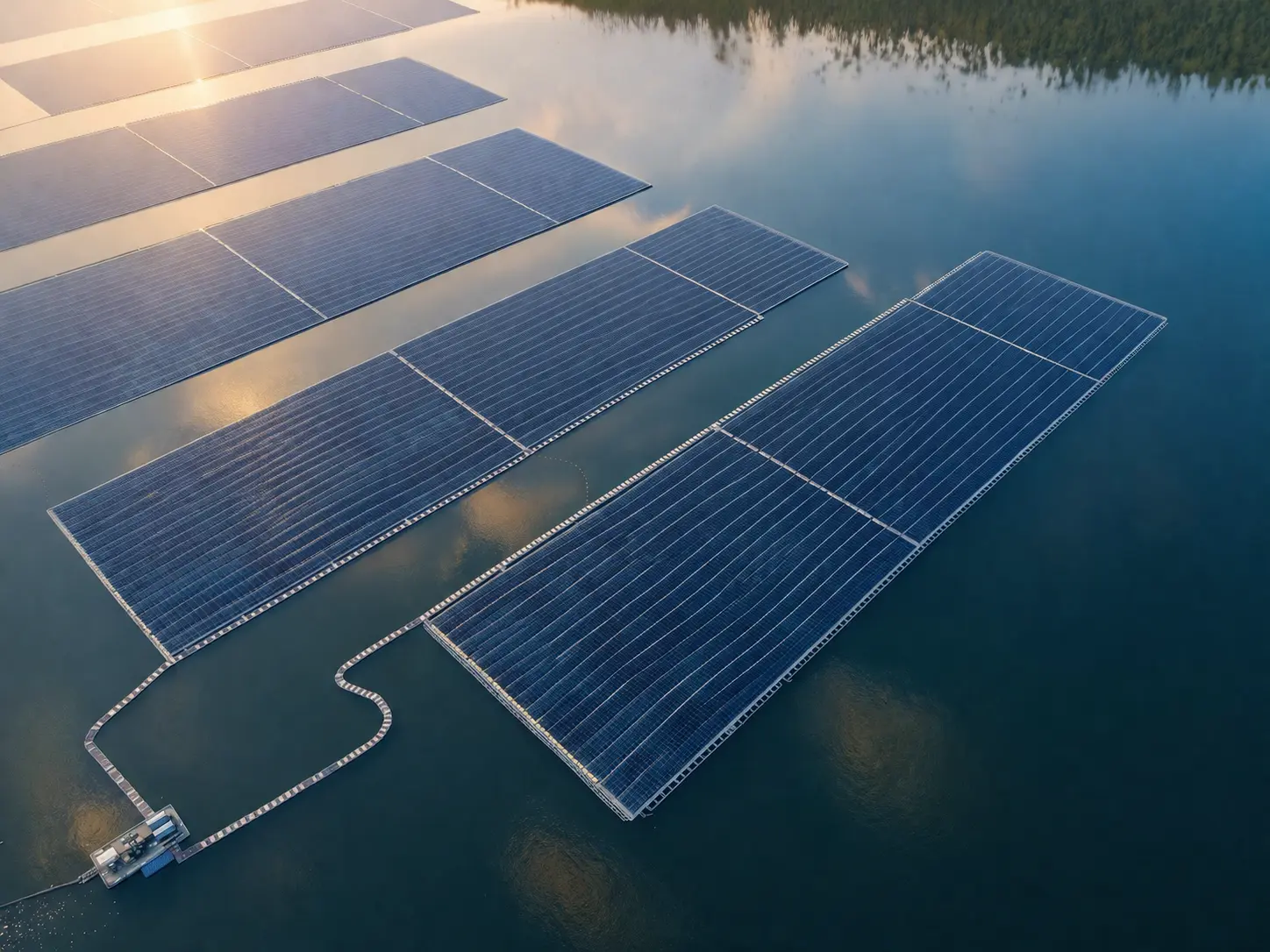
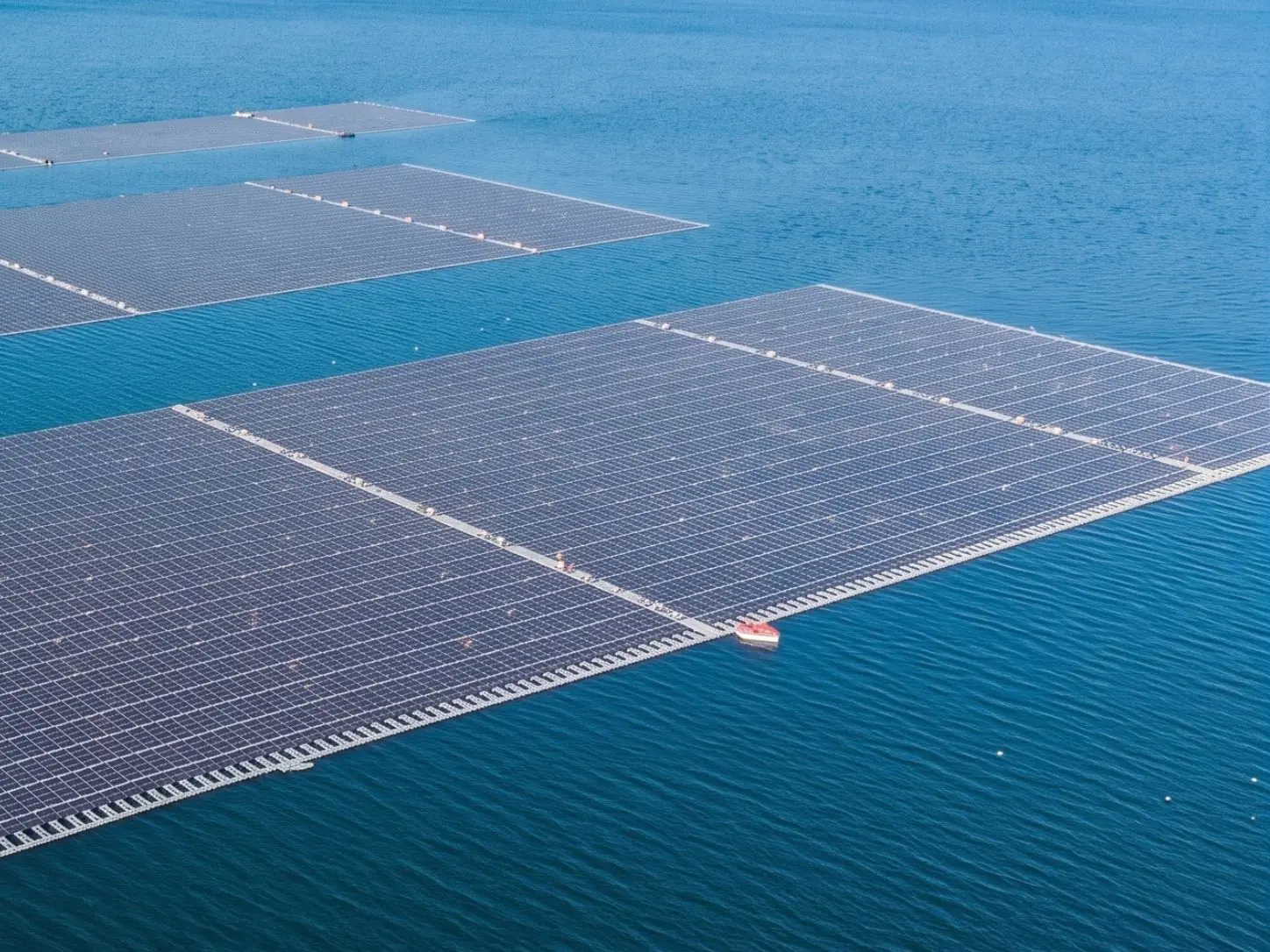
Changes in tilt and row spacing also affect shading patterns. A structure designed to optimise float stability, access, and compliance with water-body constraints may differ from a nearby land-based alternative. The model should use the actual planned layout rather than an idealised rack arrangement. Accounting for these factors helps produce a more accurate estimate of floating solar energy yield.
| Yield-model input | Ground-mounted assumption to question | Floating-solar input to verify |
|---|---|---|
| Module temperature | Generic open-rack heat-loss coefficient | Ventilation and mounting-specific thermal evidence |
| Tilt and row spacing | Optimised terrestrial rack geometry | As-designed float support angle and array layout |
| Albedo and rear irradiance | Soil or vegetation reflectance | Water surface, exposed floats, and actual rear-side view |
| Shading | Fixed land-based obstructions only | Float geometry, adjacent rows, and site-specific obstructions |
| Orientation and movement | Entirely fixed module plane | Mooring-controlled movement and whether dynamic effects are significant |
| Electrical losses | Standard cable routes and lengths | Actual array-to-platform-to-shore electrical layout |
This comparison is an engineering review aid; it does not prescribe universal floating-PV coefficients.
Include Water-Specific Losses Without Double Counting
Floating structures are exposed to conditions that may affect performance beyond cell temperature. Depending on the system design and site conditions, wave-induced movement may change the amount of sunlight reaching the modules or cause electrical mismatch between them. Any allowance for these effects should be supported by relevant design assessments and exposure data rather than applying a generic annual "wave loss" to every floating-solar installation.
Assumptions about soiling should also be supported by evidence. Some installations may be affected by bird activity, mineral deposits, splash exposure, or local water quality, while others may have different cleaning requirements. The model should not apply overlapping water-related and soiling losses to the same maintenance event without explaining why both adjustments are necessary.
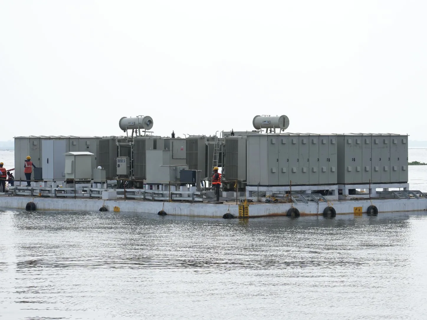
Electrical design can also affect energy yield. Cable lengths and associated electrical losses depend on the routing between the floating array, any cable equipment barge, and the shore connection. The effects of temperature, module mismatch, clipping, export limitations, and planned maintenance should be incorporated into the model using the appropriate mechanisms.
The model should clearly distinguish between:
- Energy conversion losses
- Operational unavailability
- Grid or export restrictions
These categories should not be combined into an unexplained miscellaneous allowance.
Build a Traceable Floating-PV Modelling Workflow
Do not rely on a single favourable scenario. Use a modelling process that can be repeated and checked whenever the float design changes.
- Confirm the site weather data: Choose data that represents conditions at the reservoir, including local wind and air temperature.
- Define the reference layout: Record the proposed float type, module height, tilt, spacing, array orientation, electrical configuration, and mooring assumptions.
- Set the baseline: Record the model inputs and losses, and identify which assumptions come from ground-mounted PV systems.
- Update the model for floating solar: Check the thermal coefficients, effective irradiance, shading, rear-side conditions, electrical routes, and any relevant effects of float movement.
- Run sensitivity tests: Change uncertain parameters one at a time, then test combinations where those parameters may affect one another. Do not label an arbitrarily favourable case as the expected yield.
- Establish a validation plan: Determine which measurements should be taken at the site and plant to help correct assumptions after commissioning.
This workflow does not require a new physics engine. It requires better input discipline, a clear distinction between measured and assumed effects, and cooperation between the float-design and PV/electrical-design teams. Following this process makes floating solar energy yield estimates easier to track, review, and validate.
Show Uncertainty Alongside the Yield Number
A model can calculate annual generation to many decimal places even when its inputs are uncertain. However, a precise-looking number does not necessarily mean the forecast is reliable.
When assessing bankability, resource uncertainty, the choice of temperature model, float geometry, shading, losses, availability, and long-term performance must all be considered. A P50 forecast is the annual energy yield expected to be exceeded with a 50% probability, while a P90 forecast is the yield expected to be exceeded with a 90% probability. These forecasts should be based on an appropriate uncertainty assessment and statistical method rather than an arbitrary fixed discount.
| Assumption requiring validation | Useful evidence or check |
|---|---|
| Reservoir microclimate | On-site or representative irradiance, wind, and air-temperature measurements |
| Module operating temperature | Back-of-module temperature measurements and installation-specific thermal-model calibration |
| Float-supported geometry | Approved drawings showing height, tilt, pitch, connections, and shading |
| Reflected and rear-side light | Optical assumptions suited to water and the selected module technology |
| Annual operational losses | Site-relevant O&M plan, failure assumptions, and export or availability records |
| Model accuracy after commissioning | Normalised measured-versus-predicted energy and systematic bias analysis |
Evidence requirements should be tailored to project scale and risk; this is not a prescribed measurement standard.
Once the system is commissioned, compare actual generation with the model's expected generation using the weather and operating conditions recorded during the same period, rather than relying only on typical-year weather data. Investigate long-term bias before recalibrating coefficients, and document any changes. This feedback helps improve future yield estimates without assuming that all floating systems perform alike.
Why This Matters Before Floats Are Selected
The float platform affects more than just structural procurement. The energy model is affected by module height above the water, supported tilt, air circulation, row spacing, accessibility, and the requirements for keeping the floating array in position. The resulting trade-offs must also comply with structural safety requirements, water-body limitations, and long-term maintenance needs.
Floatex Solar's floating-solar pontoon systems can be considered as part of an integrated site-assessment and engineering process. Energy yield should be assessed alongside float configuration and PV performance modelling, rather than assuming a specific improvement from water cooling before evaluating the design.
A reliable floating-solar yield study should explain three things: the expected yield, the floating-specific assumptions behind it, and the evidence that could change the results. This gives developers and financiers a more reliable basis for decision-making than a ground-mounted forecast with an arbitrary floating-solar improvement added at the end.
Ultimately, floating solar energy yield should be based on site-specific evidence, transparent assumptions, and a model that reflects the actual floating system rather than treating it like ground-mounted PV.