What it really takes to keep a solar plant working on water - year after year.
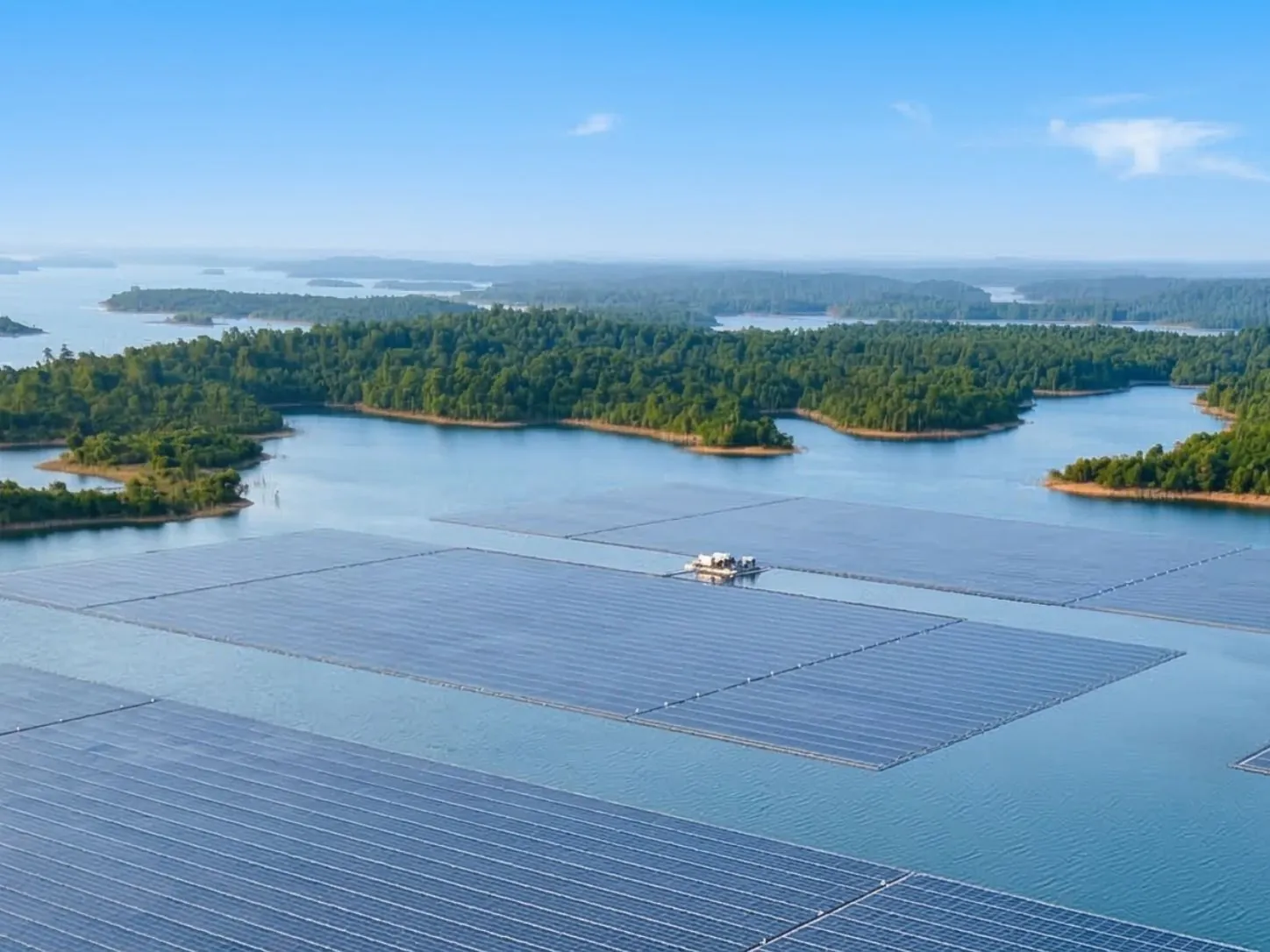
A solar array floating calmly over a reservoir is a beautiful sight. The panels lie in neat rows while the inverters deliver electricity. But commissioning day is the easy part. The real question is how that same plant will behave after years of sunlight, monsoon winds, rising and falling water, bird activity, and routine component replacement. Floating photovoltaics (FPV) began as a research idea - the first documented installation was built in Aichi, Japan, in 2007. Since then, the sector has grown from small demonstration rafts into utility-scale plants. Today, floating the module itself is not the accomplishment. The point is whether the system as a whole has been designed specifically for the water body it is placed in. Building reliable floating solar plant requires more than simply installing solar panels on water.
Reliability is a feature of the whole system and not just a float. It comes from materials, connections, mooring, electrical design, installation quality, and a maintenance plan that can actually be carried out on water.
The Original Situation: What Pilots Proved - and What They Didn't
One question early pilots were able to answer satisfactorily is that yes, electricity from the sun can be harnessed above water and save valuable land space. Larger projects then brought bigger islands, more complex mooring, and faster assembly methods. But a pilot that does well in the first season or two does not necessarily solve all the important questions regarding a 25-year lifespan:
- Can the float material retain its integrity through many years of UV and heat exposure?
- How will connectors and pins behave after millions of small wave-induced movements?
- How does the mooring behave when the reservoir dewatering takes place during the summer season?
- Can any single faulty component be replaced without stopping a large portion of the plant?
The above are some of the shortcomings. According to the 2019 Practitioner's Handbook by the World Bank, there were uncertainties with regard to durability, cost, and environmental impacts. In 2025, the IEA PVPS Task 13 review highlighted that long-term field data on performance degradation and failure are not abundant. There was also no standardized accelerated testing process for floating components. In 2026, DNV released specific standards related to float structural design and station keeping. Addressing these challenges is essential for developing reliable floating solar plants that can perform over their intended lifespan.
The Reality Check: Common Assumptions vs. Field Experience
Based on our experiences with reservoirs, canals, and industrial water bodies, here are the assumptions that we frequently need to fix:
| Common assumption | What actually happens | What it means for the project |
|---|---|---|
| "A float is just a plastic block." | Float performance depends on resin grade, UV stabilisers, wall thickness, moulding control and joint design. | Ask for material records and ageing evidence, not just the word "HDPE". |
| "Water cooling always adds 10% more energy." | Gains vary with climate, wind and airflow under the array. The range of values published is very broad, mostly just a few percent. | Treat cooling as an upside to confirm with site data, not a fixed figure in the financial model. |
| "One mooring design fits every reservoir." | The water level variation, bed soil conditions, wind fetch, and spillway currents are highly different from place to place. | Mooring must be analysed for the actual minimum, normal, and maximum water levels. |
| "Floating plants are maintenance-free." | These problems include bird fouling, fastener rusting, cable abrasions, and joint wear. | Plan boats, walkways, spares and trained crews at the design stage. |
| "If it survived the pilot, it will survive at scale." | Larger islands see different loads, longer cable runs and more complex assembly. | Treat the pilot as an experiment and use its information in the design of the real one. |
From field experience; however, actual results will vary according to site conditions and design.
Reliable Floats Start with Qualified Materials
Floats provide buoyancy, support the modules, and transfer loads between adjacent structures. HDPE is the most widely used material, but its name only reveals very little about it. A float that works well in a protected irrigation pond will not necessarily be fit for a big windy reservoir.
Four key areas of evidence should be sought by technical buyers:
- Material traceability: specification, batch data and documentation of manufacturing control.
- Environmental aging: evidence of performance under the impact of UV light, temperature and chemicals.
- Structural performance: buoyancy assessment, deformation and load-bearing capability of critical parts.
- Repairability: ability to safely inspect and replace the failed float or connector.
The purpose here is not to pass one test, but to qualify the product against a certain design basis. This is finally recognized in the recently released DNV-ST-C108 standard, which takes into account the long-term behavior of non-metallic materials. Float geometry is another important factor in terms of operation: walkway geometry, module spacing, and access to the connectors. These factors help determine whether the system can support reliable floating solar plants over the long term.
Connections Decide How the Array Behaves
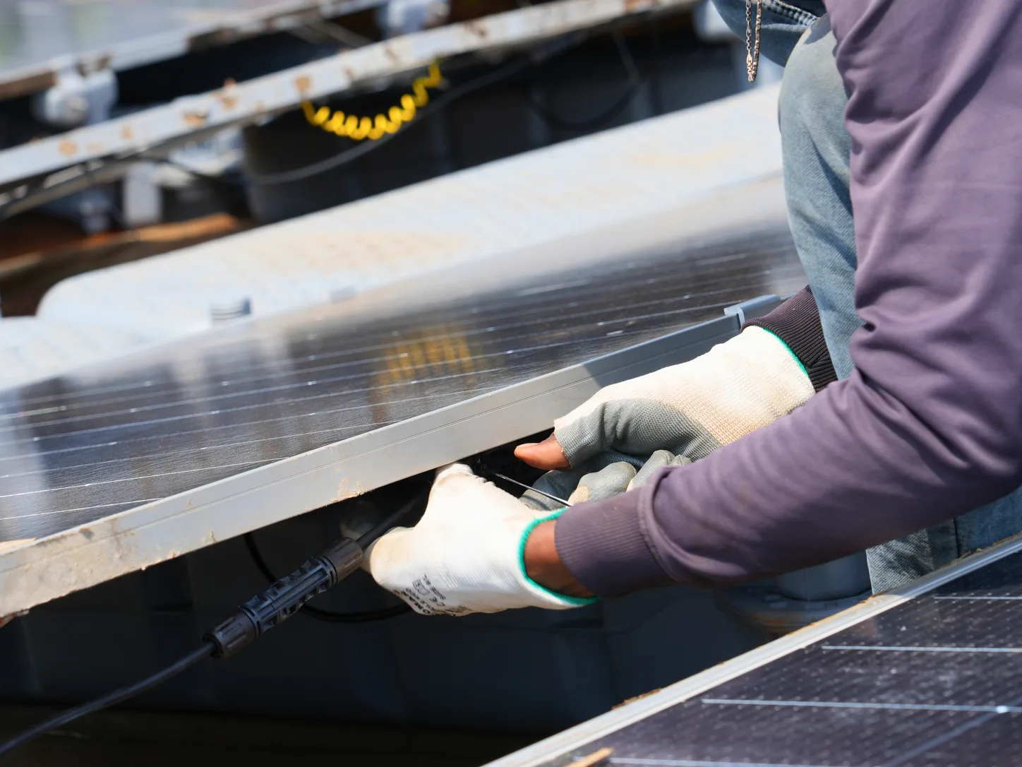
An excellent design for a float may yet end up belonging to a poorly functioning system if its connections are not strong. Pins, fastenings and joints transfer the loads, and provide the necessary freedom of motion for the array designed.
There is no absolute value in rigidity. If the joint is too stiff, it will lead to high local stresses, but if it is loose, it will cause misalignment of the array and unsafe conditions for walkways.
Connection design, island segmentation, and mooring should be engineered together - along with a clear answer to one question: if a connector fails, is the damage contained, or does it spread?
Mooring Must Suit the Reservoir, Not a Generic Rating
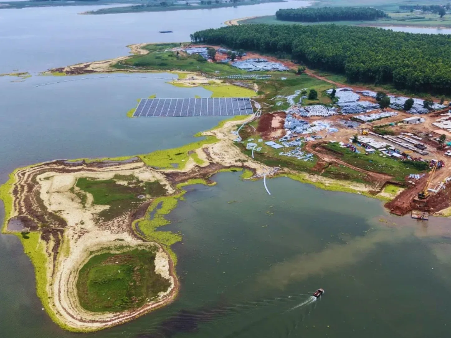
These two systems are responsible for holding the array steady and limiting its movements. A good design should be based on the local conditions such as the bathymetry, bed soil, reservoir operation levels, shore shape, wind, waves, and currents in the vicinity of intakes and spillways.
It is especially important to consider the water level variations since they may reach several meters on Indian reservoirs. As levels change, line tension and the geometry of the whole system change with them. Lines, anchors and connections must be checked across the full operating range - including making sure the array never grounds on the bed at the lowest level.
DNV-ST-E309 sets out design loads, load combinations and analysis methods for station keeping, and DNV-RP-0584 gives wider lifecycle guidance. A headline such as "designed for X km/h wind" is not proof of suitability on its own; the procurement review should examine the real site assumptions behind it.
| Element | Typical supplier claim | Evidence the project team should request |
|---|---|---|
| HDPE floats | "UV-resistant, long-life material" | Specifications, qualification results and batch traceability |
| Connectors | "Strong interlocking design" | Connection loads, permitted movement and repair procedure |
| Mooring | "Built for severe weather" | Site loads, water-level scenarios and station-keeping analysis |
| Electrical system | "Waterproof and dependable" | Environmental ratings, cable-support drawings and test records |
| Complete solution | "Engineered for decades" | Design basis, handover records and maintenance assumptions |
An editorial procurement aid - not a certification checklist or a substitute for the applicable standards.
Electrical Reliability Depends on Structural Interfaces
Electrical systems such as modules and inverters can be dealt with using standard electrical concepts. There are certain features that make water a different kind of medium from the kind used in the conventional setup.
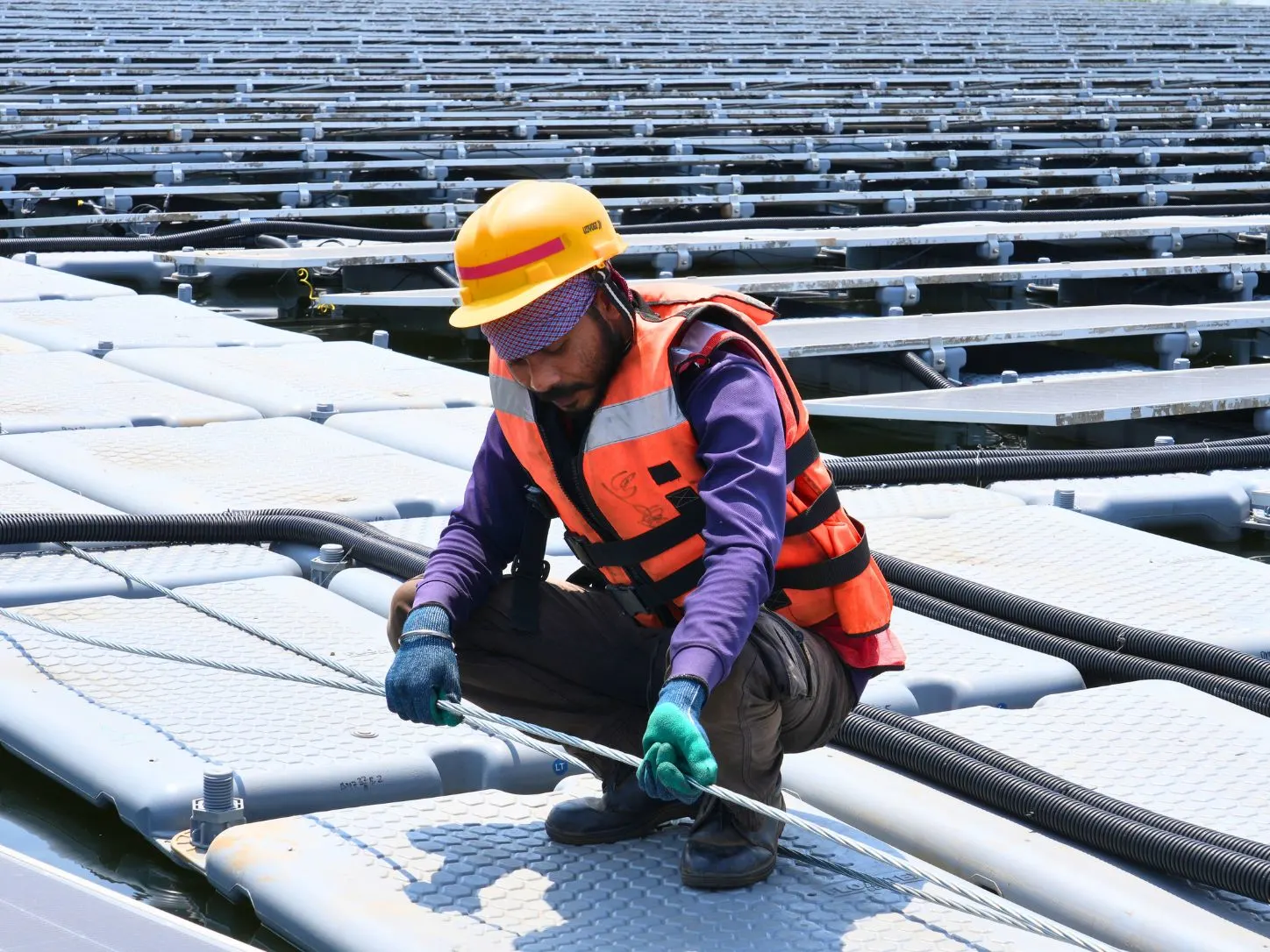
Movement of cables through moving parts, attaching them to floating units, and finally bringing them ashore are some things that should be considered. Cables should be laid and held in a manner that allows for this movement.
Earthing and equipotential bonding across moving islands need careful detailing. Such typical problems as water ingress through connectors, friction damage to cables, wear of insulation, and difficult-to-access equipment could have been easily prevented during the initial design phase rather than solved later. Properly managing these interfaces is important for reliable floating solar plants.
Design for Inspection and Replacement
Even a long lifespan for a design does not imply that nothing needs replacement. A good maintenance plan is guided by the following four questions:
- Detection: what are the signs or indicators that would show deformations, movements, damage, or electrical problems?
- Access: can the workers reach the equipment using boats and walkways?
- Replace: can one failed component be swapped without dismantling a large area?
- Restore: are spares, approved methods, and trained teams available when needed?
The inspection log becomes increasingly more useful each year. It allows you to determine whether it is an isolated defect or indicates a design problem. According to IEA PVPS, there has been recognition of the need for improved O&M data and monitoring for floating plants, and the skills like boating, diving, and marine engineering have been identified as essential. Maintenance readiness should be considered in the engineering process from the start.
Checking Reliability at Every Project Stage
An effective evaluation ties together site studies, engineering, manufacturing quality, installation documentation, and operational performance into a chain of evidence. It also helps in fixing accountability when there are multiple contractors involved.
| Project stage | Key reliability question | Useful evidence |
|---|---|---|
| Site study | What conditions must the system withstand? | Water-level history, bathymetry, soil, wind and wave studies |
| Engineering | Are float, mooring and electrical interfaces coordinated? | Drawings, load cases, calculations and risk assessments |
| Manufacturing | Are component properties consistent? | Inspection results, material records and test reports |
| Construction | Was the approved design built correctly? | Installation checks, deviation records and as-built drawings |
| Commissioning | Does the plant work as intended? | Functional and electrical test records |
| O&M | Is there a way to spot and solve deterioration in time? | Monitoring data, inspection records and maintenance history |
Evidentiary requirements and acceptance criteria will be determined by the contract, risk assessment, and regulations.
Complete records matter because defects often cross supplier boundaries. Without clear ownership of interfaces, a damaged connector or an overstressed cable becomes an issue rather than an engineering problem.
Innovation Must Improve the Whole Lifecycle
New concepts can reduce installation time, enhance float geometry, or make monitoring more effective - but there is always a cost. A lighter float is more convenient to install, but the long-term durability of such a float needs to be demonstrated. A denser arrangement utilizes the surface of water more effectively but limits access. Increased connectivity speeds up installation but increases the number of items to be inspected.
The owners need to consider both lifecycle costs and risks rather than the cost per float: inspection effort, the impact of failure, downtime, difficulty of repair, and decommissioning at the end of life. These evidence-based questions are valid for both new and existing solutions. 25 years is the target design life, not the promise that every item will work for 25 years without maintenance.
Our Approach at Floatex Solar
At Floatex Solar, we work across the full floating solar chain - site surveys, engineering, float manufacturing and installation. That gives us direct visibility of how design decisions made on paper play out on the water, and lets us take clear responsibility for the interfaces between floats, mooring and electrical systems.
We encourage every client to ask us the same questions raised in this article and to review the evidence behind our answers against the conditions of their own water body. Our focus on these engineering details supports the development of reliable floating solar plants suited to site-specific conditions.
The Real Test of a Long-Life Floating Solar Plant
More than two decades since its initial installation as research, floating solar has developed into a recognized engineering science with improved assumptions for design, component qualification, standards, and realistic O&M planning.
Floating is not the criteria of success. A reliable floating solar plant is one that has been designed for its site's real risks, is monitored honestly, and can be maintained and repaired safely throughout its operating life. Developing reliable floating solar plants depends on sound engineering, qualified components and maintenance planning that supports long-term performance.