At a Glance
50+ MW: At scale, mooring complexity rises non-linearly.
10-20 m: Averaged seasonal fluctuation of the water-level in Indian reservoirs.
25+ years: Design life requirements of mooring systems.
100-500+ anchors: Standard anchorage in utility-scale arrays.
Why Mooring Becomes the Scaling Challenge
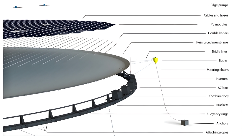
At a glance, a floating solar power plant is quite simple, a set of panels, floats, and power systems. However in reality the most complicated engineering task is behind the scenes.
Mooring systems are still fairly manageable at smaller scales (under 5 -10 MWp). This limits the number of anchor, the load cases are predictable and the design margins can be conservative enough to maintain stability.
But, when the size of the projects reaches 50 MWp and higher, the problem essentially takes a different spin.
Floating arrays covering hundreds of metres provide:
- Asymmetrical wind and wave loading.
- Dynamic contact between connected parts of the platform.
- Complex load paths throughout the structure.
- Hundreds of anchor points operating as one.
A failure at such a scale is hardly solitary. Failure of one anchor or mooring line can spread out to many other parts of the array causing instability way beyond the initial fault.
Nonetheless, mooring systems usually represent comparatively low proportion of total CAPEX – but they represent a disproportionate amount of long term operational risk. This discrepancy is among the most widespread sources of performance problems in large FSPV projects.
The Six Core Mooring Challenges at Utility Scale
1. Peak Load Concentration at the Array Perimeter
Floating solar array has uneven environmental loads. The most exposed areas, particularly towards the directions of prevailing winds, receive most of the wind and wave energy, but internal areas are partially protected.
This puts a lot of load-concentration on perimeter anchors.
In under-engineered systems, the perimeter anchors are sometimes designed to fit to average loads. In properly designed systems they are designed to the peak environmental conditions, and redundancy is added to ensure a single-point failure is not possible.
An effective approach would normally involve:
- Excessive perimeter anchoring.
- Implementing redundancy at high-load zones.
- Identification of critical stress points using load modelling.
2. Management of Mooring Geometry under Change of Water Level
The most common reservoir-based FSPV uses catenary mooring systems which are based on flexible line geometry. When water levels rise and fall, mooring lines automatically self-adjust, and that is one of the major benefits of reservoirs that experience seasonal changes.
In reservoirs with 10-20 metre water-level fluctuations, mooring lines have to operate effectively through the entire operating range. That means avoiding both:
- Too much slack at low water levels.
- Too much tension when at high levels of water.
Both conditions pose their own dangers – platform drift to structural overload.
The difficulty lies in the fact that there is no right geometry. Instead, all of the lines should be engineered to stay within safe limits under all water level, wind, and wave conditions.
It is not enough to design on average conditions. The mooring systems should be designed to accommodate the most extreme credible conditions.
3. Differential Tension Between Large Arrays
Ununiform loading does not occur very often in large floating arrays.
The wind and wave forces may differ considerably over a distance of 200-300 metres, and this will produce a difference in tension in the mooring system. A part of the array can be subjected to high stress and could be fairly stable elsewhere.
This imbalance can lead to:
- Rotational forces between the array.
- Skewed load distribution across pontoon sections.
- Localised structural stress.
Engineers normally use a zone-based mooring strategy in order to cope with this, such that the array is subdivided into various autonomous anchoring zones.
This approach:
- Constrains inter-sectional loading.
- Minimises the risks of cascading failure.
- Provides increased localised loading response.
Flexible interconnections between pontoon sections also contribute to this, where limited movement is possible without passing peak forces throughout the structure.
4. Anchor Performance in Variable Reservoir Beds
Reservoir beds are naturally non-homogenous. Even in one project site, the engineers might face:
- Low shear strength soft silts and clays.
- Layers of sand easily subjected to scouring.
- Compacted gravel or rock areas.
In large scale, the assumption of uniform conditions between hundreds of anchor points is a fatal error.
Soft sediments may cause creep or slow displacement of the anchors when they are subjected to cyclic loads. Although stronger, Sandy substrates pose the risk of scouring which diminishes the embedment depth with time.
To do it right, one should:
- Complete geotechnical site investigation (not only sampling).
- Selection of zone specific anchors.
- Localized variable embedment depths.
In practice, properly designed large systems of FSPV tend to introduce more than one type of anchor in the same project, as opposed to a single standardised system.
5. Long-Term Hardware Fatigue and Corrosion
Mooring systems have to work in a strenuous environment day and night:
- Constant moisture exposure
- UV radiation
- Temperature variation
- Cyclic mechanical loading
These conditions can seriously worsen hardware such as:
- Chains
- Shackles
- Swivels
- Connectors
On a small scale, single component replacement is not hard. On a large scale – hundreds of connection points – systemic degradation is a significant operating factor.
The first step is to spec it correctly:
- Marine grade stainless steel or galvanised fittings.
- Selection of materials depending on conditions of water chemistry and exposure.
However, specification is not enough. Structured inspection and replacement strategy is important in the long-term performance especially to wear-prone components.
6. Mooring Line Abrasion on the Reservoir Bed
Mooring lines can hang on the bottom at times of low water in reservoirs with large drawdown.
In the case of a hard substrate, gravel or rock, this poses a risk of abrasion.
Over time, abrasion can:
- Reduce chain cross-section
- Weaken structural capacity
- Lead to premature failure
This is worsened by the fact that the changing water levels shift the contact zone along the line.
There are mitigation measures such as:
- Abrasion-resistant coatings
- Application of synthetic rope portions in the areas of contact.
- Chafe protection installation.
- Bed contact minimisation by optimisation of mooring geometry.
Simulation: Verifying Design by Simulation
At a utility scale, mooring systems are too complex to be based on simplified calculations.
Projects larger than about 20 MWp are now typically done by hydrodynamic simulation.
These models enable the engineers to:
- Model wind, wave and current loading.
- Test mooring tension under operational conditions.
- Find out the key anchor zones.
- Pre-installation optimisation of system geometry.
The most important thing is not validation — it is understanding.
Simulation enables project teams to visualize the behaviour of the system under the conditions that may not yet be experienced in the field and thereby lessening uncertainty and enhancing design confidence.
Operations and Monitoring: Maintaining Performance over Time
Even an effective mooring system needs to be managed.
Conditions in the reservoir change with time because of:
- Sedimentation
- Erosion
- Operational changes
- Hardware wear
A systematic monitoring strategy is necessary to maintain a 25-year performance.
Standard best practices are:
- Regular underwater checking of anchors and connections.
- Repeat bathymetric survey to monitor the changes in sediment.
- Checking of mooring line tension at the critical points.
- Inspection of the array under extreme weather conditions.
The goal is early detection.
Dealing with problems like anchor burial or line wear during their initial phases is much cheaper than dealing with a major failure.
Conclusion
Floating solar plants are usually treated as floating solar project on a floating platform.
These challenges are all well understood; load concentration, variable geometry, differential tension, geotechnical variability, corrosion and abrasion. There are established engineering solutions to each.
The difference between successful and problematic projects is not the availability of technology, but the discipline in its use.
The projects that are predictable and consistent throughout decades are the ones that:
- Spend on thorough site research.
- Design to full operating conditions, rather than averages.
- Apply zone-based and adaptive mooring.
- Require durable, marine-grade parts.
- Introduce long-term monitoring programmes.
The mooring system is not always visible when the plant is at work, but it is what determines the structural integrity of the whole installation.
Follow us on: https://www.linkedin.com/company/floatex-solar/